Modular and Open-Source Science Station (MOSSS)
Ensuring safe stones gather moss.
The Modular and Open-Source Science Station (MOSSS) features a decentralized environmental monitoring network designed for rugged, remote terrain. Utilizing a localized LoRaWAN mesh alongside EcoWitt meteorological sensors, the system aggregates real-time microclimate data, barometric pressure, and physical movement tracking.
At the core of the MOSSS physical tracking infrastructure is the Wake on Interrupt Landslide Detector (WOILD) subsystem; an open-source hardware and telemetry framework specifically engineered to monitor slope stability and ground acceleration.
All data streams converge on a centrally located, local Home Assistant Core gateway, which orchestrates automated mobile alerts via custom vector deviation matrices and bridges the network into broader commercial smart integrations.
🛠️ Hardware Stack
| Layer | Device | Sensors / Specs |
|---|---|---|
| Field Nodes | Heltec WiFi LoRa 32 V3 | MPU6050 Accelerometer, DHT22, 1W Solar |
| Weather | EcoWitt WN90 Array | Piezo Rain, Anemometer, Temp/Humid/Pres |
| Gateways | SenseCAP M2 & EcoWitt GW3001 | LoRaWAN (TTN), WiFi |
| Core Gateway | Raspberry Pi 4 / 5 | 32GB mSD, Home Assistant Core, Nabu Casa |
🔄 How It Works (Data Pipeline)
- Telemetry Collection: Solar-powered WOILD LoRa nodes monitor environmental metrics and structural movement on hillsides, remaining in deep sleep until periodic transmission or hardware motion interrupts trigger an uplink.
- Backhaul: Data is pushed via LoRaWAN to the SenseCAP gateway (integrated with TTN), while weather data routes through the EcoWitt gateway. Remote ESP32 Wi-Fi nodes utilize encrypted Tailscale WireGuard tunnels.
- Processing & Action: Home Assistant Core ingests all streams, evaluates slope movement against real-time rainfall data via custom matrix template equations, handles local valley logic, and pushes automated alerts to mobile clients.
⚡ How the Alert Logic Works
Once deployed, the software relies on a dual-trigger mechanism to eliminate false alerts from environmental noise (such as high wind vectors or passing animals):
- The Wake-on-Interrupt Event: The physical landslide tracking node remains silent in deep sleep until an active geometric slope or acceleration threshold is crossed, waking up instantly to blast an alert payload (
stateMode = 1or2) via LoRaWAN or ESPHome. - The Vector Deviation Matrix Evaluation: Home Assistant intercepts the payload using the
databrokerchannel, runs it through internal matrix template equations, evaluates concurrent localized rain accumulation rate from your EcoWitt array, and instantly fires a high-priority mobile notification if both thresholds match critical slope-failure parameters.
🚀 Step-by-Step Deployment Roadmap
After purchasing all necessary hardware, assemble a MOSSS station from raw parts and field deploy it following these these sequential steps:
- Hardware Assembly & Sensor Construction: Order parts, build physical enclosures, wire your Heltec V3 board, and connect accelerometers and environmental sensors.
- Set-up Home Assistant Server (Provision Central Gateway): Install HAOS, create the
databrokerM2M user account, and configure 30-day recorder filters before bringing field nodes online. - Establish Remote Connections Using NabuCasa (recommended), Tailscale VPN, or DDNS with port forwarding, setup remote access to your HA instance.
- Integrate Commercial Smart Equipment: Unbox, power up, and integrate off-the-shelf meteorological, agricultural, or scientific hardware—such as the EcoWitt GW3001 weather station gateway—directly into Home Assistant to establish real-time microlocal metrics (rainfall, wind vectors, barometric pressure, …).
- Add WiFi sensors with ESPHome (Optional): Set up option-based Wi-Fi or Tailscale VPN nodes using ESPHome.
- Setup TTN and LoRa transmissions: Set-up TTN LoRa communication. Navigate to https://nam1.cloud.thethings.network and create an account. If no public gateway is available, setup your TTN LoRa gateway. Create an application and link it to the HA TTN integration using the application id, API Key, and TTN server address.
- Flash WOILD v1.1.6 Firmware & Calibrate: Configure your LoRaWAN credentials (
DevEUI,AppEUI,AppKey), assign unique node IDs (NODE_ID), set static baseline orientation angles, and flash the MCU via Arduino IDE or PlatformIO. Then, openWOILD_v1.1.6_payload_formatter.jsin../software/Landslide-Detectors/and paste the decoder script into your TTN or ChirpStack uplink payload formatter console. - Field Installation & Alert Verification: Mount hardware nodes at your field station, run physical tilt/motion interrupt tests, and verify real-time data ingestion and vector deviation matrix alerting on your Home Assistant dashboard.
👉 Let’s get started! Proceed to Chapter 1: Hardware and BoM
🛠️ Chapter 1: MOSSS Hardware Deployment & Bill of Materials (BoM)
This chapter contains the physical infrastructure designs, schematic references, and hardware requirements for the Modular and Open-Source Science Station (MOSSS) framework.
To deploy a standard operational tracking cell, you will need components for three distinct layers: the physical telemetry edge nodes (WOILD), the microclimate parsing node (EcoWitt), and the localized gateway hub.
📋 Comprehensive Bill of Materials (BoM)
1. WOILD Edge Nodes (Per Node)
These low-power field units are custom-fabricated to monitor earth movement and acceleration over remote slopes. Total cost per node is about $70.00.
| Component | Quantity | Description / Function | Key Specification | Est. Unit Cost (USD) |
|---|---|---|---|---|
| MCU Development Board | 1 | Core microprocessor processing telemetry and deep-sleep states. | Heltec WiFi LoRa 32 V3 (Must support external RTC GPIO interrupts) | $20.00 |
| Inclinometer / Accelerometer | 1 | Senses ground acceleration and shifts; outputs low-pulse hardware interrupt. | MPU6050 breakout board | $4.00 |
| Custom 2-Layer PCB | 1 | Integrates MCU, power regulation, and sensor lines (See gerber files). | FR-4 substrate, ENIG finish (highly recommended for high humidity) | $15.00 |
| Power Storage | 1 | High-capacity outdoor power delivery. | 3.7V 18650 Li-ion battery (2500mAh+), with 2 pin, 2.54 mm pitch JST | $10.00 |
| Solar Harvesting | 1 | Charges internal cells under light canopy tracking conditions. | 5V 1W to 2W Monocrystalline solar panel | $3.00 |
| Humidity Sensor | 1 | Detects water in enclosure. | DHT22 breakout board | $2.00 |
| Solar Charger | 1 | Manages solar power and battery charging. | CN3065 solar charge board | $2.00 |
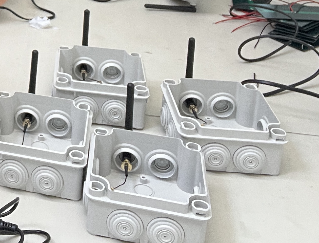
| Enclosure | 1 | Ruggedized environmental protection box. | IP67/IP68 weatherproof junction box with cable glands | $5.00 - $10.00 |
| 4.7 kOhm resistor | 2 | Used to pull up SDA and SCL pins for I2C | Must solder to through holes of PCB | $0.10 |
| Female Header Pins | 3 | Soldered to PCB to accept boards | 40 pin, 2.54 mm pitch | $0.75 |
| Screw Terminal Block | 2 | Solder to PCB for solar and tripwire | 2 pin, 5 mm | $0.25 |
| JST Battery Connector | 1 | Solder to CN3065 for battery connection | 2 pin, 1.25 mm pitch | $0.30 |
| 22 AWG Wire | 1 | Solder to solar pannel | 2 Conductor, tinned, 10 meters | $10.00 |
| Tripwire | 1 | Disconnected audio port serves as tripwire | 1/8“ audio TRS extender, 6 ft | $2.00 |
2. Meteorological Subsystem (Per Site)
Aggregates hyper-local microclimate data and makes them available online.
| Component | Description / Function | Key Specification | Est. Unit Cost (USD) |
|---|---|---|---|
| EcoWitt Weather Station | Solid-state array and WiFi Gateway | GW3000 with WS90 7-in-1 Sensor Array | $200.00 |
3. Central Gateway Hub (Per Grid)
The edge-computing collection facility responsible for the GUI, data collection and distribution, LoRa transmission accumulation, and automated emergency alerts.
| Component | Description / Function | Key Specification | Est. Unit Cost (USD) |
|---|---|---|---|
| Edge Server Platform | Dedicated machine running Home Assistant. | Raspberry Pi 4 (4GB+) | $160.00 |
| LoRaWAN Gateway | Acts as the local network concentrator to intercept WOILD node signals. | SenseCAP M2 indoor LoRa gateway or similar multichannnel gateway | $70.00 - $120.00 |
🔌 Critical Circuit Interconnect Requirements
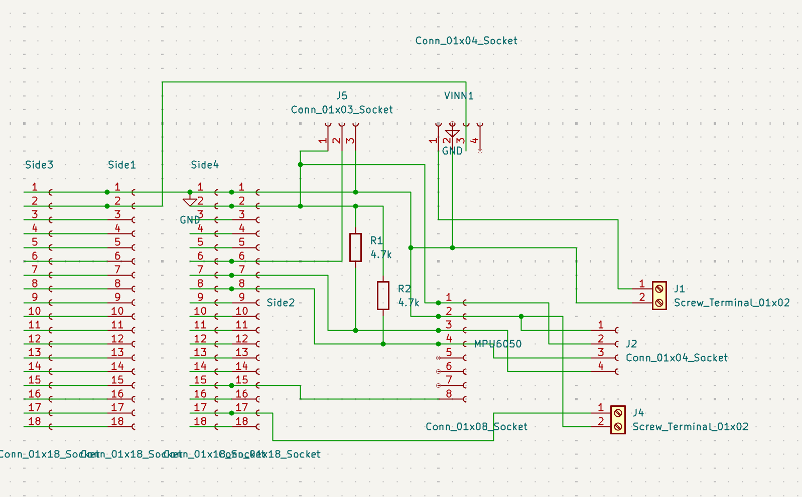
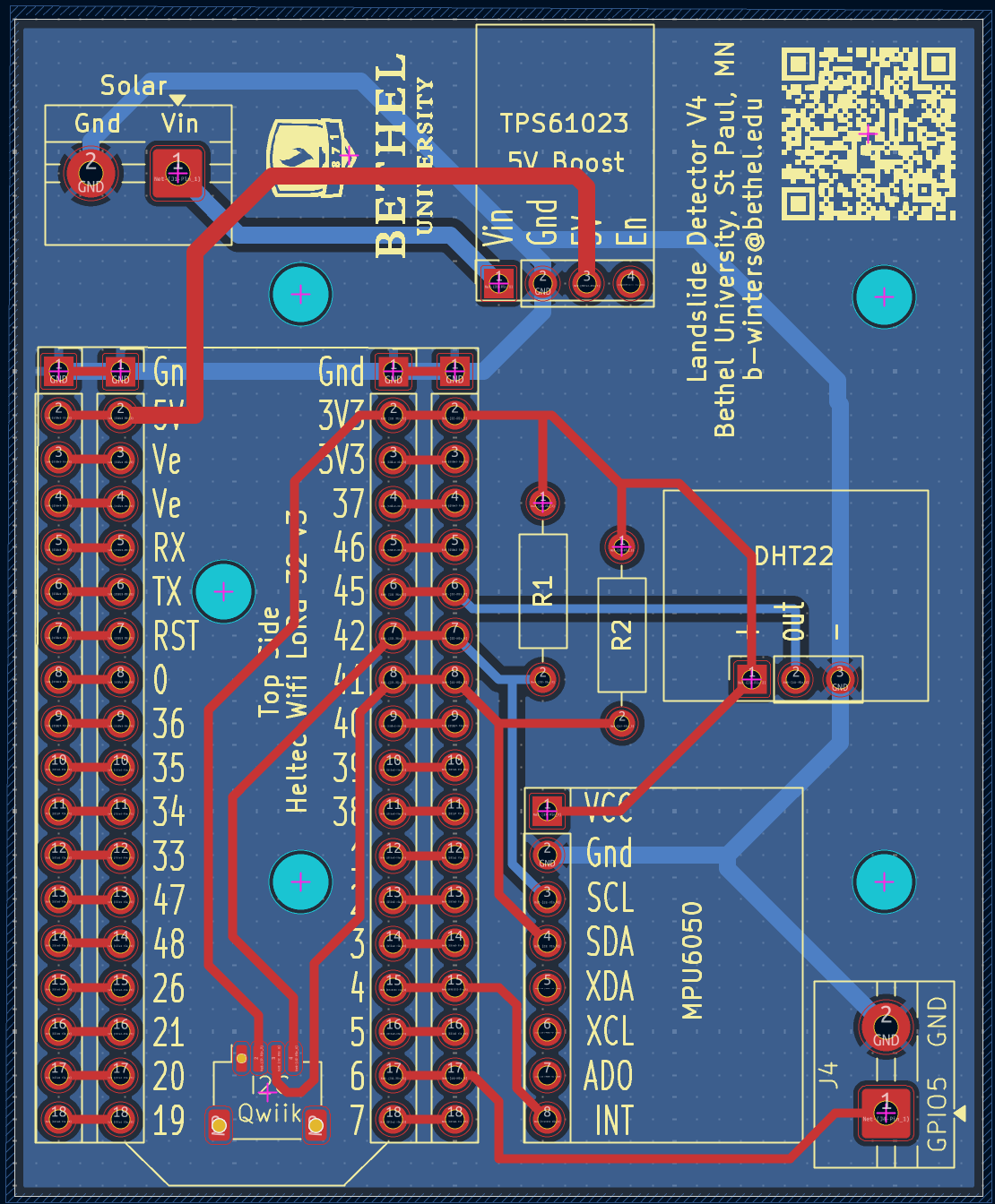
To successfully leverage the ultra-low-power Wake on Interrupt performance characteristics of the WOILD node ($<700\mu\text{A}$ current draw while asleep), verify your PCB layout complies with the following trace paths:
- The Interrupt Rail: Connect the
INTpin of your accelerometer module directly to an RTC-capable GPIO pin on the microprocessor board (e.g., GPIO 12, 14, or 15 on a standard ESP32). Non-RTC pins cannot capture states when the core processor clock is powered down. - I2C Interface: Establish direct lines from
SDAandSCLpins with appropriate $4.7\text{k}\Omega$ pull-up resistors to maintain baseline data stability when checking telemetry frames. - Power-Gating Transistors: Implement a P-channel MOSFET network to cut off parasitic current leaking into the LoRa module during deep-sleep monitoring intervals.
PCB MANUFACTURING & ORDERING GUIDE
This directory contains the production-ready Gerber files exported from KiCad for the Multi-Node Landslide Detection hardware. You can use the included ZIP archive to order custom printed circuit boards from any standard quick-turn PCB fabrication house.
RECOMMENDED FABRICATION HOUSES
The exported files use standard RS-274X/X2 formats, compatible with all major global manufacturers. Popular high-quality options include:
- JLCPCB (jlcpcb.com)
- PCBWay (pcbway.com)
- OSH Park (oshpark.com) - Perfect for high-precision, US-made prototypes
🛠️ WOILD Node v4 Hardware Design
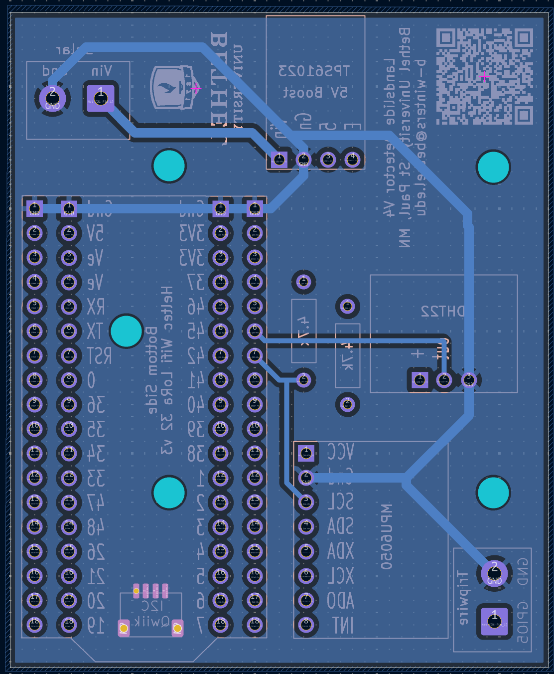
The hardware subsystem is engineered to bridge abstract telemetry logic with resilient environmental deployment. The panel matrix below tracks our complete progression from the baseline circuit traces to our physical field installation array.
|
1. Circuit Logic
|
2. Enclosures
|
|
3. PCB Top Side
|
4. PCB Bottom Side
|
STEP-BY-STEP ORDERING INSTRUCTIONS
-
Locate the Archive:
- Find and download the bundled Gerber zip file in this directory. Do NOT unzip it.
-
Upload to the Fabricator:
- Navigate to your chosen manufacturer’s website and click on their “PCB Instant Quote” or “Order Now” tool.
- Drag and drop the untouched .zip file directly into their online Gerber viewer upload box.
-
Verify the Upload:
- Most modern fabricators will automatically parse the zip archive and display a live visual preview of the top and bottom layers of the board.
- Ensure the board dimensions are automatically and correctly detected by the online system.
RECOMMENDED FABRICATION SPECIFICATIONS (PRODUCTION SETTINGS)
When completing the configuration form on the manufacturer’s website, use the following baseline settings to ensure physical reliability in outdoor terrain:
- Material Type: FR-4 (Standard)
- Layer Count: 2 Layers (Double-sided)
- PCB Thickness: 1.6 mm (Standard thickness for rugged field enclosures)
- Surface Finish: HASL with lead (Cost-effective) OR ENIG (Electroless Nickel Immersion Gold). –> NOTE: ENIG is strongly recommended if you are deploying nodes in highly humid, tropical environments, as it offers superior oxidation resistance.
- Copper Weight: 1 oz (Standard)
- Solder Mask Color: Your choice (Green, Blue, Black, etc. Does not affect performance)
- Silkscreen Color: White (Or contrasting color for component label readability)
COMPONENT SOURCING (BoM & CPL)
- Component Placement: The board layout utilizes clear silkscreen labeling identifying resistor, capacitor, microcontroller, and sensor pinouts.
- Assembly: This board is optimized for hand-soldering. If you intend to use an automated turn-key assembly service (PCBA), you will need to provide the manufacturer with the Bill of Materials (BoM) and Component Placement List (CPL / Centroid file) exported separately from the main design repository. ==============================================================================
👉 Proceed to Chapter 2: Home Assistant Setup
🏠 Chapter 2: Home Assistant Setup
Configure the Home Assistant Gateway
This chapter covers the initial physical provisioning and bare-metal OS installation for the central Modular and Open-Source Science Station (MOSSS) edge gateway. As such, it walks through:
- Installation of Home Assistant OS (HAOS) on a Raspberry Pi 4 or 5.
- Establishing two-tiered login access.
- Creating a dedicated Machine-to-Machine (M2M) profile called
Data Broker(login:databroker) under Settings > People to handle incoming data streams securely.
⚠️ CRITICAL ORDERING: Adhere strictly to the sequence below. Misordering these setup steps will result in a failed headless boot or network mismatch.
🏠 Stage 1: Home Assistant OS Bare-Metal Installation
📋 Prerequisites & Hardware Checklist
Before beginning, ensure your central hub hardware components match our verified specifications:
- Single Board Computer: Raspberry Pi 4 or Raspberry Pi 5 (Minimum 4GB RAM recommended).
- Power Supply: Official Raspberry Pi USB-C power supply (15W for Pi 4, 27W for Pi 5) to prevent undervoltage failures.
- Storage: A 32GB high-endurance microSD card (UHS Speed Class 3 / V30 or better rated for continuous write cycles) or an external USB 3.0 SSD.
- Network: An Ethernet cable connected directly to your local network switch/router for initial provisioning.
💿 Installation Step-by-Step
Because the gateway needs to compute vector matrices locally without internet dependence, we utilize the bare-metal Home Assistant Operating System (HAOS).
-
1. Download the Flashing Tool
Requires Mac, Windows, or Linux PC
Download and install the official Raspberry Pi Imager from raspberrypi.com/software. Insert your storage media into your flashing computer. -
2. Select the HAOS Image
Do not use default Pi OS
- Launch the Imager tool. (note: formatting may be required to continue)
- Click Choose Device and select your model (e.g., Raspberry Pi 4).
- Click Choose OS, scroll down to select Other specific-purpose OS, click Home Automation, click Home Assistant, select Home Assistant OS.
-
3. Flash without OS Customization
Crucial Step
Select your target storage device and click Next.
⚠️ CRITICAL: If the imager prompts you to apply OS customization settings (like setting up Wi-Fi or SSH), select NO. HAOS manages its own network initialization—applying custom configurations through the imager will corrupt the system container structure. Confirm and write the image.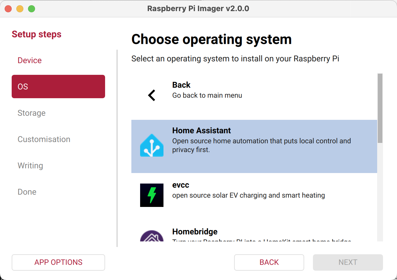
-
4. Headless Initial Boot
Takes 5-15 minutes
Insert the flashed storage into your Raspberry Pi. Connect an Ethernet cable to your router, then plug in the power supply. The Pi will boot headlessly; give it up to 15 minutes to automatically provision, unpack the environment, and fetch system dependencies. -
5. Complete Onboarding UI
Web Browser Setup
On a computer connected to the same local network, open a browser window and navigate to:http://homeassistant.local:8123*(If the hostname fails to resolve, check your router's DHCP client list to find the Pi's IP address and navigate tohttp://YOUR_PI_IP:8123).* Follow the prompts to create your local admin account.
🔐 Stage 2: Operational Security (OpSec) & Network Provisioning
Once you have landed on your fresh Home Assistant dashboard and created your main owner account, advance to user provisioning and system networking:
This section defines the access permissions, secure data pipelines, and remote connectivity meshes required to protect the MOSSS gateway hub from corruption while allowing open scientific collaboration.
🛡️ Multi-Tiered User Access Tiers
Configure these explicit profiles under Settings > People on your newly installed dashboard:
1. Research Partner Profiles (Admin)
- Access Level: Administrative configuration rights.
- Deployment: System owner and shared strictly with active field engineers and collaborative research institution partners to tweak template filters or debug physical sensor links.
2. Public Observation Profile (User / Non-Admin)
- Access Level: Read-Only view rights (Dashboard visualization access only).
- Deployment: Provided to local community leaders, public donors, or visiting scientists. Completely blocks out system configuration menus, preventing accidental damage.
3. Machine-to-Machine (M2M) Data Pipeline (databroker)
- Access Level: Non-admin, Data Authentication Account (Bypasses human UI interaction entirely).
- Deployment Name:
databroker - Crucial Setup: This profile handles incoming data streams from both your local network and remote field assets. Whether your nodes are feeding data locally via the Mosquitto Broker or connecting from remote field sectors using ESPHome Tailscale configurations, they use the
databrokercredentials to securely authenticate their data payloads.
⚠️ SECURITY COMPLIANCE WARNING: Never reuse the credentials for
databrokeron human user profiles. Isolating your automated data pipeline ensures that even if an external field node is physically tampered with, your core gateway administration remains entirely secure.
👉 Proceed to Chapter 3.1: Home Assistant Integrations
🧩 Chapter 3.1: Home Assistant Integrations
This chapter details the software application layer, native integrations, and community integrations of Home Assistant, which is responsible for running the Modular and Open-Source Science Station (MOSSS) central gateway ecosystem. This configuration translates incoming data into local vector matrices and safety alerts.
📱 Layer 1: Home Assistant Mobile Companion App
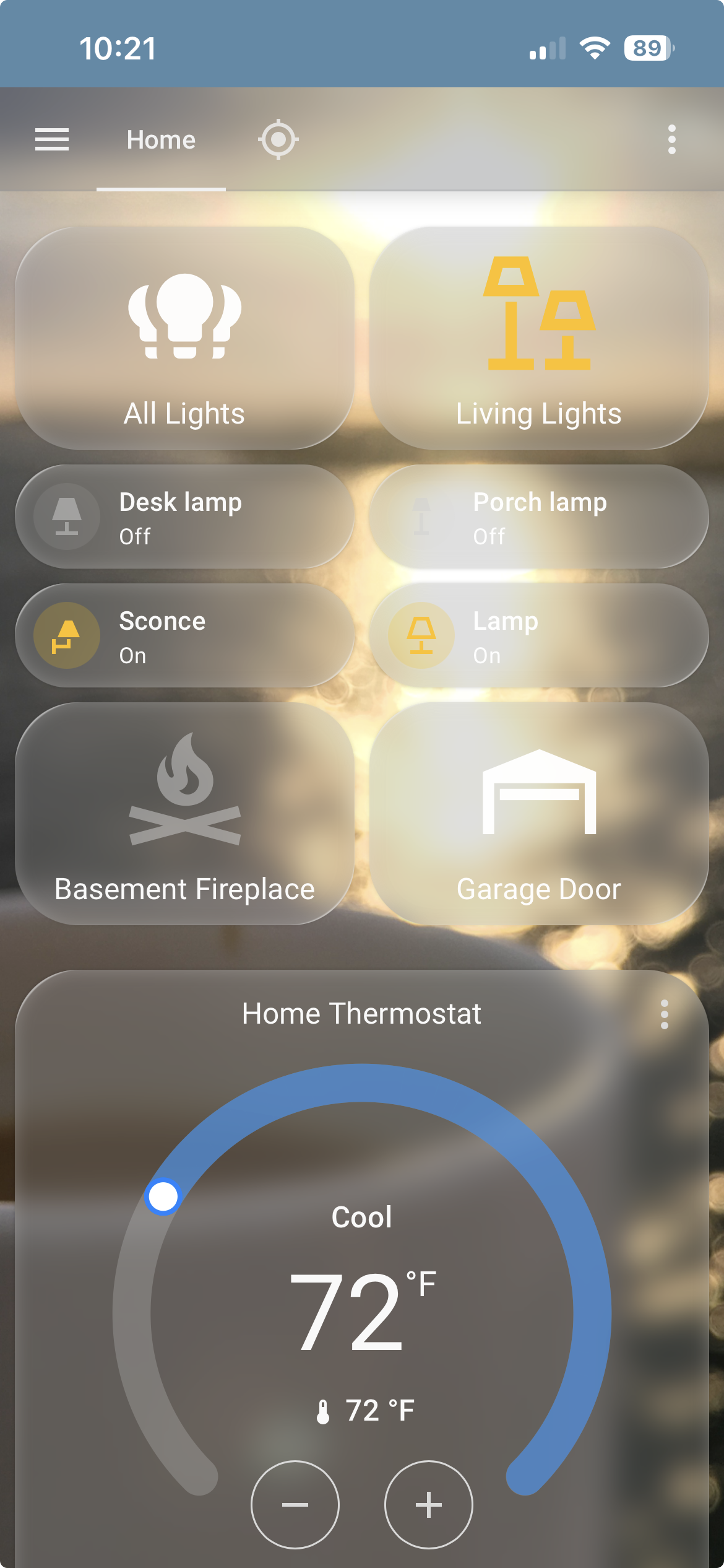
- Mobile App Integration: Links localized system notifications directly to the Home Assistant Companion App on field-technician smartphones. This setup bypasses standard cloud delivery delays to fire high-priority critical alerts with custom alert sounds immediately upon matrix breach.
Step 1: Download the App
- iOS / iPadOS: Search for Home Assistant in the Apple App Store.
- Android: Search for Home Assistant in the Google Play Store.
Step 2: Local Network Connection
- Connect your mobile device to the same local Wi-Fi network as your Home Assistant server.
- Launch the app. It will automatically scan your subnet and discover your gateway (e.g.,
http://homeassistant.local:8123orhttp://192.168.x.x:8123). - Select your instance and authenticate with your administrator credentials.
- Enable requested permissions (Notifications, Location, and Background Refresh) so the app can register critical push alert channels and update presence sensors.
Remote Access will be covered later in Chapter 3.2
🔌 Layer 2: Home Assistant Integrations
Finding and Installing Native Integrations in Home Assistant
Native integrations are official components built directly into Home Assistant, requiring no third-party repositories or external store installations.
Suggested native integrations include:
- EcoWitt: Captures hyper-local meteorological data (temperature, humidity, rain rate, wind metrics) directly from local network broadcasts via the GW3001 gateway or local webhooks.
- Weather.com: Pulls regional atmospheric data and historical forecasting projections to complement microclimate array readings.
- Home Assistant Supervisor & Backup: Handles core OS container maintenance, system health, and automated daily database backups.
- Raspberry Pi Hardware & Power Supply Checker: Monitors gateway hardware thermals, CPU metrics, and reports undervoltage issues to protect storage integrity.
- Sun: Calculates solar elevation vectors, daylight hours, and astronomical data used to track field array solar harvesting performance.
- Meteorologisk Institutt: Provides native local weather forecasting and ambient meteorological baseline tracking.
- MQTT (Mosquitto Broker): See chapter 4: MQTT Bridges external data streams—such as LoRaWAN field node telemetry routed through The Things Network (TTN)—directly into Home Assistant.
- RESTful Sensor / API Framework: Enables cloud-based data ingestion (
rest.yaml) from off-grid gateways like the GW3001 when deployed outside the local network subnet. - System Housekeeping Tools (Bluetooth, Local IP, Radio Browser, Shopping List): System-level native components managing local connectivity, gateway network parameters, and auxiliary entities.
- The Things Network Used to connect TTN edge nodes (eg. WOILD Sensors) to your Home Assistant Instance. Setup is addressed in Chapter 4.3: TTN and LoRa.
Step-by-Step Installation
-
Navigate to Integrations: In your Home Assistant sidebar, go to Settings → Devices & Services.
-
Add New Integration: Click the + Add Integration button in the bottom-right corner of the Integrations tab.
-
Search & Select: Type the name of the service, protocol, or device brand in the search bar (e.g., Ecowitt, Weather.com, Sun, or MQTT).
-
Configure Credentials: Follow the on-screen wizard to input required authentication details (such as local IP addresses, API keys, or user login tokens).
-
Assign Area (Optional): Once set up, Home Assistant will prompt you to assign the newly discovered entities or devices to a specific Area (e.g., Outdoors or Gateway Station).
💡 Auto-Discovery Note: Many local hardware devices (like HomeKit accessories, Philips Hue hubs, or local network gateways) will automatically trigger a notification card at the top of the Devices & Services page as soon as they join your local subnet—allowing one-click setup without manual searching.
🌦️ EcoWitt GW3001 Integration Setup
🏠 Method 1: Local Network Integration (Native Webhook)
Use this method when the EcoWitt GW3001 gateway and your Home Assistant server reside on the same local network subnet.
Step 1: Configure Custom Webhook in WS View Plus
- Open the WS View Plus (or EcoWitt) mobile app on a device connected to the local Wi-Fi network.
- Select your GW3001 gateway device from the list.
- Navigate to Menu → Customized (or Weather Services → Customized).
- Enable the custom upload service and enter the following settings:
- Protocol Type:
Ecowitt - Server IP / Hostname:
<YOUR_HOME_ASSISTANT_LOCAL_IP>(e.g.,192.168.1.100) - Path:
/api/webhook/ecowitt - Port:
8123(or your local custom HA port) - Upload Interval:
300seconds
- Protocol Type:
- Save and apply the configuration.
Step 2: Enable Integration in Home Assistant
- In Home Assistant, go to Settings → Devices & Services.
- Click Add Integration in the bottom right corner.
- Search for Ecowitt and select it.
- Confirm the prompt to complete setup. Home Assistant will begin auto-discovering sensor channels as the GW3001 sends webhook payloads.
☁️ Method 2: Remote Deployment (RESTful Cloud API)
Use this method when the GW3001 is deployed at a remote, off-grid, or field station lacking a direct local network link back to Home Assistant. See Layer 3: Apps & File Editor for details about finding and editing YAML files.
1. Generate Application Key & API Key
-
Log into your account at ecowitt.net.
-
Click your profile icon/avatar in the top-right corner and select User Center (or Profile).
-
Navigate to the API Management tab in the sidebar menu.
-
Application Key: Click Create Application Key to generate a client identifier string.
-
API Key: Click Create API Key to generate your personal data authorization token.
-
Locate Your GW3001 MAC Address
- Via WS View Plus App: Open the app → Device List → locate GW3001 MAC address (
X1:X2:X3:X4:X5:X6). - Via EcoWitt Web Portal: Log into ecowitt.net → Device Settings (gear icon) → view MAC address.
- Via WS View Plus App: Open the app → Device List → locate GW3001 MAC address (
-
Add rest.yaml to Home Assistant
- Download or prepare your
rest.yamlfile. Copy ours here, but make sure you replace YOUR_APP_KEY, YOUR_API_KEY, and YOUR_MAC_ADDRESS with your actual values. - In Home Assistant, open File Editor and create a new file named
rest.yamlin the root folder alongsideconfiguration.yaml. - Copy the full contents into your newly created
rest.yamlfile and save. - Ensure your
configuration.yamlincludes the line:rest: !include rest.yaml. - Verify via Settings → Developer Tools → YAML → Check Configuration.
- If valid, restart Home Assistant or perform a Quick Reload.
- Download or prepare your
📦 Layer 3: Home Assistant Apps (Add-ons)
These applications run as isolated system containers managed by the Home Assistant Supervisor to provide local backend utilities. They include the following possible installs:
-
File Editor: Provides a direct, lightweight web editor workspace to create, update, and manage your core configuration files (
configuration.yaml,rest.yaml,templates.yaml,automations.yaml). They can be copied here -
Studio Code Server (VS Code): Serves as an advanced, full-featured code editor add-on for editing YAML scripts, managing runtime directory structures, and debugging syntax directly within Home Assistant.
-
Mosquitto Broker: Runs an isolated local MQTT broker container to ingest raw telemetry payload strings (such as LoRaWAN data from TTN) and route them to Home Assistant’s internal databroker M2M channel. More detailed information found in Chapter 4: MQTT.
-
Samba Share: Exposes the Home Assistant root configuration folders over the local network, allowing technicians to map directory drives and manage system files securely from an external PC.
-
Tailscale / WireGuard (VPN Add-ons): Creates secure, encrypted mesh network tunnels to allow field technicians direct, remote access to the local Home Assistant instance from cellular or satellite networks. More detailed information found in Chapter 3: Remote Access.
-
File Editor / Studio Code Server: Provides a direct editor workspace to securely update configuration scripts and manage local asset logs inside the
software/Home-Assistant/Runtime-Configurationdirectory.
📦 Finding and Installing Add-ons in Home Assistant
Add-ons (also referred to as Apps in updated Home Assistant UI releases) are isolated Docker containers managed directly by the Home Assistant Supervisor. They run alongside Home Assistant Core to add system utilities, database brokers, and file management tools.
⚠️ Requirement: Add-ons are only available on Home Assistant OS (HAOS) or Home Assistant Supervised installation types.
Step-by-Step Installation Guide
-
Access the Add-on Store:
- In your Home Assistant sidebar, navigate to Settings → Add-ons (or Apps).
- Click the Add-on Store (or Install App) button in the bottom-right corner.
-
Search for the Application:
- Browse through the default Official or Community repository lists, or use the search bar at the top to type the name of the tool (e.g., Mosquitto broker, File editor, Samba share, or Studio Code Server).
-
Install the Add-on:
- Select the application card from the search results to open its information page.
- Click the INSTALL button.
-
Configure Settings:
- Open the Configuration tab at the top of the add-on page to set required options (such as setting passwords for Samba share or defining ports for Mosquitto).
- Click Save to apply your parameters.
-
Start and Enable Options:
- Return to the Info tab.
- Toggle Show in sidebar if you want direct access from the main navigation panel (recommended for File Editor and Studio Code Server).
- Toggle Start on boot and Watchdog so the container automatically runs and restarts if it crashes.
- Click START to launch the container.
Adding Custom Third-Party Repositories
If an add-on is hosted outside the official store repositories:
- Go to Settings → Apps → Add-on Store.
- Click the three dots menu (
⋮) in the top-right corner and select Repositories. - Paste the URL of the third-party GitHub repository and click Add.
- The newly added tools will now appear at the bottom of the store list for installation.
🧩 Layer 4: Home Assistant Community Store (HACS)
Deploys as our secondary package manager to unlock community-driven custom cards, integrations, and advanced backend tools not available in the core distribution line. This includes:
- UI eXtension (UIX) & card-mod: Injects custom CSS styling directly into the Home Assistant DOM to dynamically alter visual card elements, warning indicators, and background colors.
- visionOS & iOS Liquid Glass Theme: Provides a high-readability visual wrapper with a transparent glassmorphic layout tailored for low-light command monitoring environments.
- Weather Radar Card: Displays live, interactive radar precipitation scans alongside weather sensor metrics to track approaching storm cells.
- Clock Weather Card: Integrates dynamic real-time clock displays alongside localized meteorological sensor readouts.
- Horizon Card: Renders solar elevation vectors, dawn/dusk intervals, and astronomical metrics to analyze field node solar panel charging efficiency.
- Map Card: Tracks spatial locations using geospatial coordinates (X, Y) for active WOILD nodes, automatically highlighting nodes in red when vector deviation thresholds trip.
- Embedded Webpage Card (Windy.com): Renders live wind vectors and barometric weather models directly inside the dashboard UI without requiring external API processing.
🔐 INSTALLATION PREREQUISITE: To initialize the HACS environment on a fresh installation, you must have a valid GitHub Account. The setup process requires you to authenticate the local gateway using GitHub’s secure OAuth device-pairing key protocol before the community repository manager can unlock.
🧩 Installing Custom Elements via HACS (Home Assistant Community Store)
HACS serves as a community package manager to download custom integrations, themes, and frontend UI cards that are not available in the official Home Assistant Core distribution.
Initial Setup & Prerequisites
- Prerequisite: Ensure you have a free GitHub Account ready for authentication.
- Install HACS Integration:
- Navigate to Settings → Devices & Services → Add Integration.
- Search for HACS.
- Follow the prompt to copy the device activation code, open the provided GitHub authorization link (
github.com/login/device), and authenticate the gateway.
- Sidebar Access: Once authorized, a dedicated HACS tab will appear in your Home Assistant main sidebar.
Step-by-Step Installation of HACS Resources
-
Open the HACS Panel: Click HACS in your sidebar navigation panel.
-
Search for Elements:
- Click the Search bar or select the filter category (e.g., Integrations or Frontend).
- Type the name of the desired resource (such as card-mod, Weather Radar Card, or Clock Weather Card).
-
Download Resource:
- Select the resource card from the search results.
- Click Download (or Download with HACS) in the bottom right corner.
- Select the latest release version and confirm the download.
-
Activate the Installed Resource:
- For Frontend Cards & Themes: Refresh your web browser (
Ctrl + F5orCmd + Shift + R) to force Home Assistant to load the new JavaScript resources. - For Custom Integrations: Restart Home Assistant (Settings → System → Restart), then navigate to Settings → Devices & Services → Add Integration to finish setting up the newly installed integration.
- For Frontend Cards & Themes: Refresh your web browser (
Adding Unlisted Custom Repositories
If a custom frontend card or integration is not listed in the default HACS store:
- Open HACS from the sidebar.
- Click the three dots menu (
⋮) in the top-right corner and select Custom repositories. - Paste the URL of the GitHub repository (e.g.,
https://github.com/author/custom-card). - Select the category (Integration or Dashboard / Lovelace) and click Add.
- The resource will now appear in your HACS search results ready for download.
👉 Proceed to Chapter 3.2: Remote Access
☁️ Chapter 3.2: Remote Access & Network Architecture
To ensure field technicians and operators can securely monitor landslide tracking grids from anywhere globally, the gateway utilizes a redundant, dual-path remote access design tailored to bypass complex network security limitations.
Architecture Components
1. Home Assistant Cloud / Nabu Casa (Primary Pipeline)
- Function: Serves as the primary encrypted pipeline for zero-configuration remote monitoring.
- Mechanism: Provides a direct, authenticated web link (
https://[your-subdomain].ui.nabu.casa) to the field station dashboard, safely bypassing local firewall modifications or open ports.
2. Tailscale / WireGuard (Secondary / Advanced Mesh VPN)
- Function: Provisions an independent, encrypted WireGuard mesh VPN network (
100.x.x.xprivate range). - Primary Use Case: Connects remote ESPHome sensors and external MQTT I/O devices (e.g., ESP32-S3 boards) deployed across separate cellular or satellite relays. Microcontrollers compiled with the
esphome-tailscalecomponent communicate directly with the gateway’s static Tailscale IP without requiring public DNS records or port forwarding.
⚠️ CRITICAL DEPLOYMENT WARNING
Nabu Casa must be fully initialized and authenticated before activating Tailscale links on the host server. Activating Tailscale during initial Nabu Casa provisioning can alter host system routing matrices, preventing Home Assistant Cloud from establishing its remote tunnel. Keep Tailscale inactive during initial setup.
Field & Off-Grid Deployment Steps
Select and configure one of the following remote endpoint options based on your field site requirements:
Option A: Home Assistant Cloud / Nabu Casa (Automated)
- Navigate to Settings → Home Assistant Cloud in the web UI and log in to your account.
- The Home Assistant Companion App automatically ingests the encrypted Nabu Casa endpoint URL.
- The app dynamically routes traffic between the local IP and the remote cloud endpoint depending on connection state.
Option B: Tailscale / WireGuard VPN (Encrypted Mesh)
- Navigate to Settings → Add-ons (or Apps) and install the Tailscale or WireGuard add-on.
- Install the matching client application on the mobile or field device.
- Authenticate the node to establish the encrypted mesh tunnel, enabling direct local HA IP access over cellular or satellite relays.
Option C: Reverse Proxy / Dynamic DNS (Custom Endpoint)
- Establish a public domain entry using Cloudflare Tunnels, NGINX Reverse Proxy, or DuckDNS paired with SSL certificates.
- Open the mobile companion app and navigate to Settings → Companion App → [Server Name].
- In the External URL field, input your public domain endpoint (e.g.,
https://my-field-station.duckdns.org).
⚠️ Risks, Trade-offs & Limitations Summary
| Option | Primary Risks | System Limitations & Trade-offs |
|---|---|---|
| Option A: Nabu Casa | Publicly reachable login page; subdomains can be enumerated via public DNS records if credentials or MFA are weak. | Requires a recurring monthly subscription ($6.50/mo); fully dependent on Nabu Casa infrastructure availability. |
| Option B: Tailscale Mesh | Central account control (if your Tailscale/SSO account is breached, all mesh nodes are accessible). | Requires the Tailscale client application to be installed and actively running on every mobile or field device; non-admin users cannot easily access via a bare browser link. |
| Option C: DDNS & Port Forwarding | High attack surface; directly exposes Home Assistant to public internet port scanners, credential stuffing, and unpatched zero-day exploits. | Dynamic public IPs can change before DDNS syncs; requires manual router/firewall configuration; local SSL setup often causes internal IP certificate warnings. |
👉 Proceed to Chapter 4.1: MQTT
🦟 Chapter 4.1: MQTT Integration & Payload Processing
MQTT (Message Queuing Telemetry Transport) is a lightweight, publish-subscribe messaging protocol designed specifically for low-bandwidth, high-latency, or unreliable networks. It serves as the primary machine-to-machine (M2M) communication layer within the MOSSS infrastructure, bridging long-range LoRaWAN telemetry networks directly with the Home Assistant automation engine.
📡 Architecture & Telemetry Pipeline
Rather than maintaining direct HTTP connections from distributed hardware, our system relies on a local Mosquitto MQTT broker to route telemetry asynchronously:
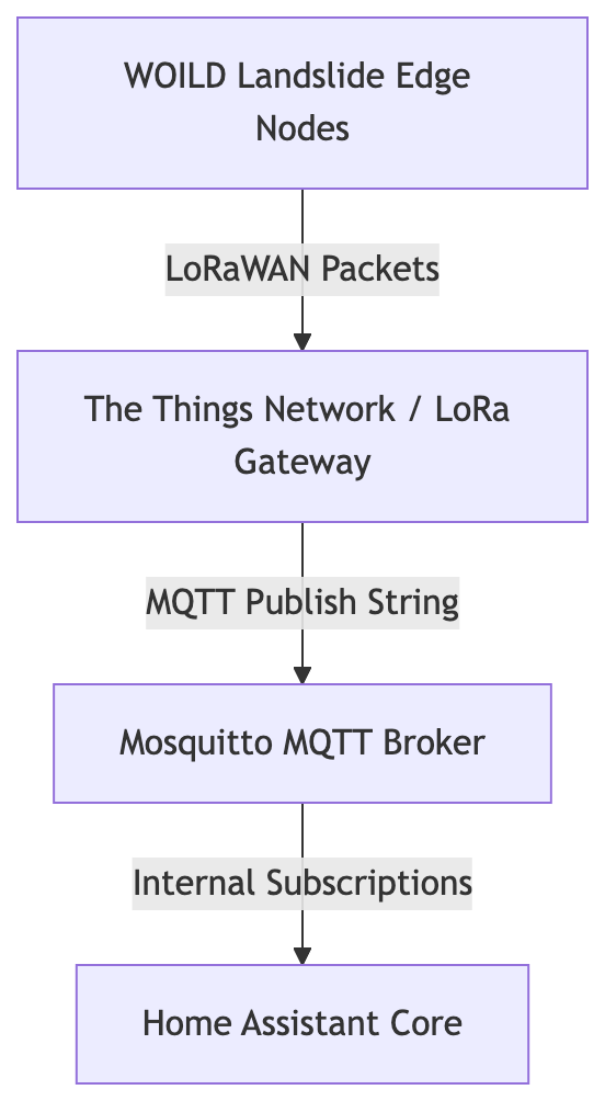
- LoRaWAN & The Things Network (TTN) Bridging: Physical WOILD landslide edge nodes transmit telemetry packets via LoRaWAN to a local gateway/TTN. TTN then funnels these JSON payloads directly to our local Mosquitto broker using dedicated
databrokerM2M credentials to update tracking matrices instantly. - Microcontroller Telemetry: Standalone ESP32/ESP8266 boards or specialized field sensor kits publish readings directly to specific MQTT topics without requiring complex REST API handshakes.
- Decoupled Architecture: Home Assistant subscribes to topics (e.g.,
mosss/field/node01/telemetry) to update internal sensor entities in real time without polling delays.
⚙️ Step-by-Step Mosquitto Broker Setup
Setting up MQTT involves running the local broker container and linking it to Home Assistant.
Step 1: Install Mosquitto Broker Add-on
- In Home Assistant, navigate to Settings → Add-ons → Add-on Store.
- Search for Mosquitto broker.
- Click Install.
- In the Info tab, toggle Start on boot and Watchdog ON.
- Click START to initialize the container.
Step 2: Create an MQTT System User
For security, MQTT clients must authenticate before publishing data to the broker:
- Go to Settings → People → Users. (Note: If “Users” is hidden, enable Advanced Mode under your User Profile).
- Click Add User in the bottom right.
- Enter a username (e.g.,
mqtt-userordatabroker) and a secure password. - Click Create.
Step 3: Configure the Native Integration
- Go to Settings → Devices & Services.
- Click Add Integration and search for MQTT.
- Confirm the configuration—Home Assistant will automatically detect the local Mosquitto add-on and prompt you to enable it using the credentials created above.
🛠️ Defining MQTT Sensors in YAML
Once the broker is operational, define incoming telemetry endpoints in configuration.yaml or an included mqtt.yaml file:
mqtt:
  sensor:
    - name: "Field Node 01 Battery Voltage"
      state_topic: "mosss/field/node01/telemetry"
      value_template: "{{ value_json.battery_v }}"
      unit_of_measurement: "V"
      device_class: "voltage"

    - name: "Field Node 01 Tilt X-Axis"
      state_topic: "mosss/field/node01/telemetry"
      value_template: "{{ value_json.tilt_x }}"
      unit_of_measurement: "°"
🖥️ GUI Alternatives to YAML Configuration
If you prefer not to edit configuration.yaml directly, Home Assistant offers two graphical UI options to set up MQTT sensors.
Method 1: The Native MQTT ‘Add Device’ UI Subentry
Home Assistant allows you to add custom MQTT entities directly from the MQTT integration page without touching configuration files.
- Go to Settings → Devices & Services.
- Click on the MQTT integration card.
- Click Add Entry (or Add MQTT Device depending on your Home Assistant version).
- Fill out the device fields:
- Device Name: e.g.,
Field Node 01 - State Topic:
mosss/field/node01/telemetry - Value Template:
{{ value_json.battery_v }} - Unit of Measurement:
V - Device Class:
voltage
- Device Name: e.g.,
- Click Submit. Home Assistant will generate the entity automatically.
Method 2: MQTT Auto-Discovery (Zero-Configuration GUI)
Instead of manually defining sensors in Home Assistant, your field devices or script can publish a single JSON “discovery payload” to the broker when booting up. Home Assistant automatically picks this up and generates the GUI entities with zero user interaction.
How it works:
The device publishes a JSON configuration string to the prefix homeassistant/sensor/[device_id]/config.
Example Discovery Payload:
- Topic:
homeassistant/sensor/field_node_01_batt/config - Payload:
{
  "name": "Field Node 01 Battery Voltage",
  "state_topic": "mosss/field/node01/telemetry",
  "value_template": "{{ value_json.battery_v }}",
  "unit_of_measurement": "V",
  "device_class": "voltage",
  "unique_id": "field_node_01_battery"
}
Once published, the entity sensor.field_node_01_battery_voltage instantly appears under Settings → Devices & Services → MQTT.
💡 Comparison: YAML vs. GUI Methods
| Feature | configuration.yaml | Native MQTT UI Subentry | MQTT Auto-Discovery |
|---|---|---|---|
| Ease of Setup | Moderate (Requires file editor) | High (Form-based) | Highest (Fully automated) |
| Version Control | Easy (Git/backup friendly) | Stored in internal HA database | Stored in internal HA database |
| Best For | Static home networks | Quick manual additions | Scalable multi-node field deployments |
⚠️ Crucial MQTT Concepts for Beginners
The “Retain Flag” Trap
- What it is: When an MQTT client publishes a payload with the
retain: trueflag, the broker stores that message permanently. Any new subscriber (or Home Assistant upon reboot) immediately receives that old message. - The Pitfall: Setting
retain: trueon rapid sensor telemetry can cause “ghost entities” or outdated data to re-populate long after a sensor has been taken offline. - Best Practice: Only set
retain: truefor state-change configurations or static switch states. Keepretain: false(default) for continuous sensor streams like battery voltage or tilt data.
👉 Proceed to Chapter 4.2: ESPHome
🤖 Chapter 4.2: ESPHome IDE
ESPHome is a system that lets you control your microcontroller boards (such as ESP32 and ESP8266) using simple, powerful YAML configuration files. In the MOSSS architecture, ESPHome allows field microcontrollers—like the ESP32-S3 paired with environmental sensors—to communicate back to Home Assistant seamlessly over local Wi-Fi, MQTT brokers, or encrypted remote mesh networks.
The Home Assistant ESPHome App gives users access to an integrated development environment (IDE) within the HA user interface directly and provides a mechanism for over-the-air (OTA) firmware updates.
📐 Deployment Architectures
We provide three primary ESPHome deployment configurations based on an ESP32-S3 microcontroller paired with a BME680 environmental sensor (Temperature, Pressure, Humidity, Gas Resistance). Choose the architecture that aligns with your field network topology:
| Feature | Option A (esphome-wifi-bme680.yaml) | Option B (esphome-mqtt-bme680.yaml) | Option C (esphome-tailscale.yaml) |
|---|---|---|---|
| Primary Protocol | Native Home Assistant API | MQTT Broker (1883 / 8883) | Native HA API over Tailscale VPN |
| Scope | Local Network Only | Local or Remote | Remote Multi-Site |
| Network Dependency | Direct LAN connection | Access to central MQTT Broker | Tailscale Mesh Network |
| Encryption | Noise Protocol (API Key) | Optional TLS (Port 8883) | WireGuard / Tailscale Mesh |
| HA Auto-Discovery | Yes (mDNS / Native) | Yes (MQTT Discovery) | Yes (via VPN Subnet) |
| On-Board Diagnostics | None | Status LED (GPIO48) | Status LED (GPIO48) + Identify Button |
🛠️ Configuration Breakdown & Use Cases
Option A: Standard Local Network Deployment esphome-wifi-bme680.yaml
- Best For: Simple indoor or local outdoor setups where the ESP32 and Home Assistant reside on the exact same Wi-Fi subnet.
- Mechanism: Uses Home Assistant’s native API over direct TCP sockets. Automatically discovered via mDNS.
- Requirements: Home Assistant must be on the same local network subnet.
Option B: Decoupled / External Broker Deployment esphome-mqtt-bme680.yaml
- Best For: Environments without direct HA network access, multi-broker topologies, or cloud-hosted instances (e.g., AWS, DigitalOcean, or public MQTT relays).
- Mechanism: Pushes sensor updates directly to an MQTT broker. Home Assistant reads data via the native MQTT Integration using Home Assistant MQTT Discovery.
- Requirements: Requires a reachable MQTT broker IP/domain and valid authentication credentials.
Option C: Secure Remote Multi-Site Deployment esphome-tailscale.yaml
- Best For: Secure, off-site deployments (remote field stations, secondary properties, or cellular gateways) that need to communicate with Home Assistant securely across the public internet.
- Mechanism: Compiles the
esphome-tailscalecomponent directly onto the ESP32-S3. On boot, the board joins your private Tailscale mesh network (100.x.x.xrange), creating an encrypted WireGuard tunnel back to your Home Assistant gateway. - Diagnostics: Includes an onboard RGB LED “Identify” button sequence on GPIO48 to quickly locate physical hardware units in multi-node field fleets.
⚙️ Step-by-Step Hardware Provisioning & Setup
Step 1: Set Up secrets.yaml
To keep sensitive credentials out of version control, create or update secrets.yaml inside your ESPHome working directory (/config/esphome/):
# Network Credentials
wifi_ssid: "YOUR_WIFI_SSID"
wifi_password: "YOUR_WIFI_PASSWORD"
wifi_ap_password: "YOUR_FALLBACK_AP_PASSWORD"

# Security & API
esphome_api_key: "YOUR_32_BYTE_BASE64_KEY="
esphome_ota_password: "YOUR_OTA_PASSWORD"

# MQTT Parameters (If using Option B)
mqtt_broker_ip: "100.X.X.X" # Or public domain/IP
mqtt_password: "YOUR_MQTT_PASSWORD"

# Tailscale Auth Key (If using Option C)
tailscale_auth_key: "tskey-auth-YOUR_REUSABLE_TAILSCALE_KEY"
Step 2: Provision & Flash Remote ESP32 Devices
- Navigate to your ESPHome dashboard or workspace directory (
https://github.com/wint0178/Modular-Open-Source-Science-Station/tree/main/software/ESPHome/). - Open your targeted configuration file (e.g.,
esphome-tailscale-bme680.yaml) and update thenameandfriendly_namevariables to match your deployment site. Ensure all secrets variables correctly reference yoursecrets.yaml. - Compile and flash your ESP32-S3 board over USB or OTA.
- On initial boot, the board will attach to the local Wi-Fi, initialize the sensor pipeline, and automatically establish its communications link back to the central server.
⚠️ Essential ESPHome Operational Rules
1. Initial Flash vs. OTA (Over-the-Air) Updates
- Initial Flash: A brand-new, unprogrammed micro-controller must be connected via a physical USB cable to perform the first firmware install.
- OTA Updates: After the initial USB installation is complete, all subsequent updates can be compiled and sent wirelessly over Wi-Fi (Over-the-Air).
2. Wi-Fi Fallback AP (Captive Portal)
- What Happens During Network Failure: If a field board loses its primary Wi-Fi connection, ESPHome automatically spins up a local fallback Wi-Fi access point (e.g.,
MOSSS-Field-AP). - Field Recovery: Rather than retrieving the physical node to re-flash it via USB, a technician can connect a smartphone directly to the board’s fallback Wi-Fi AP to reconfigure credentials through a browser captive portal.
👉 Proceed to Chapter 4.3: TTN LoRa
🛰️ Chapter 4.3: TTN & LoRaWAN Integration
LoRaWAN (Long Range Wide Area Network) is a low-power, long-range wireless protocol engineered for battery-operated field devices transmitting small payloads over long distances. In the MOSSS architecture, LoRaWAN acts as our primary telemetry link for off-grid, long-range landslide monitoring sensors (such as WOILD edge nodes) deployed beyond the reach of local Wi-Fi or cellular connections.
The Things Network (TTN) serves as our decentralized network server layer, ingesting raw LoRa gateway RF packets, managing device encryption keys, decoding payloads, and forwarding structured JSON data directly to our local Mosquitto MQTT broker or Home Assistant instance.
📡 LoRa vs. LoRaWAN Fundamentals
To understand how telemetry travels from the field to our server, it is helpful to distinguish between the physical radio technology and the network protocol:
| Concept | OSI Layer | Function |
|---|---|---|
| LoRa (Long Range) | Layer 1 (Physical) | Proprietary radio frequency modulation using Chirp Spread Spectrum (CSS). Operates on unlicensed sub-GHz ISM bands (915 MHz US / 868 MHz EU). |
| LoRaWAN | Layer 2/3 (MAC & Network) | Open standard network protocol managing device security, channel selection, gateway routing, and server uplinks. |
Device Classes & Power Management
LoRaWAN end-devices operate under three distinct behavioral classes depending on power availability:
- Class A (Battery / Solar - Default): Devices sleep continuously and wake up only to transmit an uplink. Receiver rx-windows open briefly right after transmitting. Lowest power consumption; ideal for WOILD field nodes.
- Class B (Scheduled Beaconing): Devices open periodic receiver windows synchronized with the gateway for downlinks.
- Class C (Continuous Listening): Device radio receiver remains constantly awake. Highest power consumption; requires main power (e.g., Gateways).
📐 Architecture & Data Pipeline
Field telemetry traverses a multi-stage pipeline from physical sensor actuation to Home Assistant dashboard display:
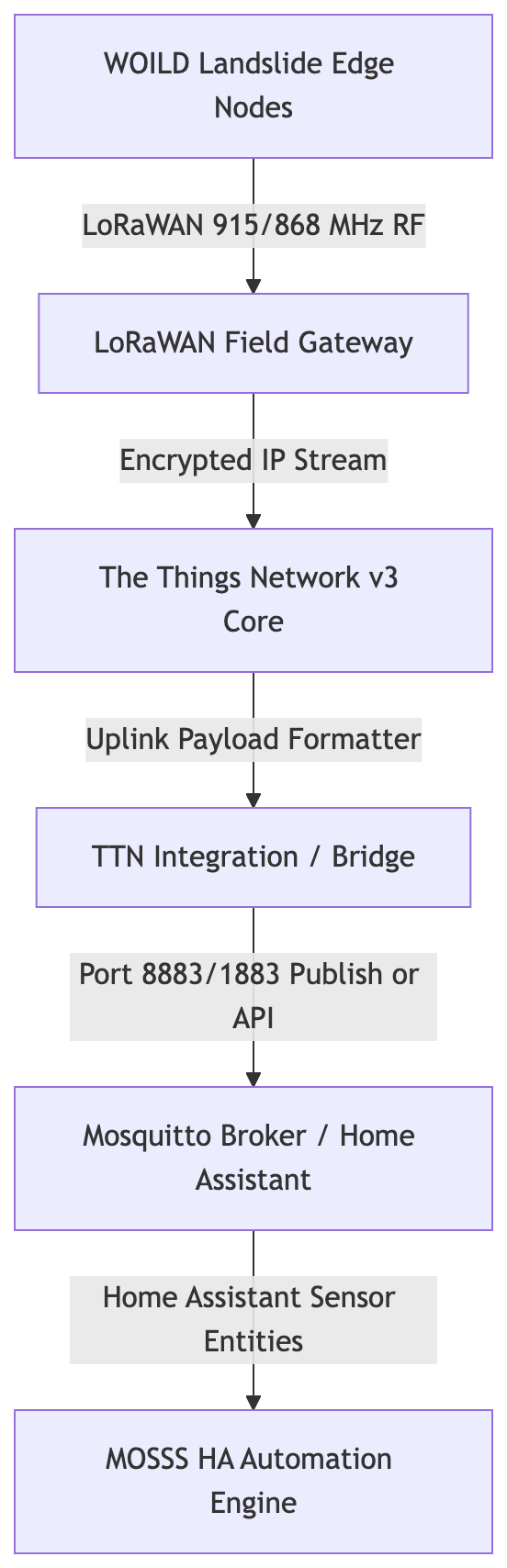
- Edge Nodes (WOILD): Battery/solar-powered microcontrollers equipped with tilt sensors, soil moisture probes, and battery monitors transmitting at sub-GHz frequencies (e.g., US915 / EU868).
- LoRaWAN Gateway: Ingests long-range radio packets within a 2–10 km line-of-sight radius and forwards them via Ethernet, Wi-Fi, or Cellular backhaul to TTN.
- The Things Network (TTN): Handles Join Requests (OTAA), validates message integrity, and executes JavaScript payload formatters to convert raw binary bytes into JSON keys.
- MOSSS Integration Layer: Bridges TTN decoded payloads into local Home Assistant sensor entities via MQTT or native polling APIs.
🛠️ TTN Console Setup & Device Configuration
Step 1: Create Application & Register Gateway
- Log into your The Things Network (TTN) Console.
- Navigate to Gateways → Register Gateway and input your gateway’s EUI (found on the physical sticker or gateway interface).
- Select your region’s frequency plan (e.g.,
United States 902-928 MHz, FSB 2orEurope 863-870 MHz). - Navigate to Applications → Add Application and create a container (e.g.,
mosss-landslide-monitoring).
Step 2: Register Field Devices (OTAA)
We strongly recommend Over-The-Air Activation (OTAA) for secure key negotiation:
- Inside your TTN Application, click Devices → Register Device.
- Input device identification parameters:
- DevEUI: Unique 64-bit hardware ID burned into the node.
- AppEUI / JoinEUI: Application ID identifier.
- AppKey: 128-bit root key used to generate session keys.
Step 3: Configure Payload Formatter (Uplink Decoder)
LoRaWAN transmits raw byte arrays to minimize airtime. In the TTN Console under Payload Formatters → Uplink, add a JavaScript decoder to convert raw bytes to JSON before forwarding to Home Assistant. Pre-configured payload formatters in JS format are provided for each WOILD version in their respective software folders:
function decodeUplink(input) {
  var bytes = input.bytes;

  // Decode Battery Voltage (Bytes 0-1 as unsigned int, divided by 1000)
  var rawBattery = (bytes[0] << 8) | bytes[1];
  var batteryV = rawBattery / 1000.0;

  // Decode X-Axis Tilt Angle (Bytes 2-3 as signed int, divided by 10)
  var rawTiltX = (bytes[2] << 8) | bytes[3];
  if (rawTiltX & 0x8000) rawTiltX -= 0x10000; // Sign extend for negative values
  var tiltX = rawTiltX / 10.0;

  return {
    data: {
      battery_v: batteryV,
      tilt_x: tiltX
    }
  };
}
⚙️ Connecting TTN to Home Assistant
You can integrate TTN into your Home Assistant environment using either a direct local MQTT bridge or the native GUI-based storage integration. Instructions for adding individual sensing notes to TTN are covered later, in Chapter 5: WOILD Firmware.
Method 1: Local MQTT Broker Bridge (Recommended for Real-Time Pipelines)
Option A: Direct TTN MQTT Subscription
- In TTN Console, go to Integrations → MQTT.
- Note the Public TLS Address (e.g.,
nam1.cloud.thethings.network:8883) and generate an API Key with “Grant all rights” or “Read uplink traffic”. - Add a topic subscription in Home Assistant’s native MQTT integration for your TTN application path:
v3/{application_id}@ttn/devices/{device_id}/up
Option B: Mosquitto Broker Bridging (mosquitto.conf)
Add a broker-to-broker bridge definition in your local Mosquitto configuration to pull TTN messages into local channels automatically:
connection ttn-bridge
address nam1.cloud.thethings.network:8883
bridge_account_share false
remote_username mosss-landslide-monitoring@ttn
remote_password NNSXS.YOUR_GENERATED_TTN_API_KEY
bridge_cafile /etc/ssl/certs/ca-certificates.crt
topic v3/+/devices/+/up in 0 mosss/field/ ttn/
Method 2: Native Home Assistant TTN Storage Integration (GUI Setup)
The official Home Assistant The Things Network (TTN) integration pulls decoded sensor payloads directly from TTN’s Storage API using the native graphical interface without requiring custom broker bridge configurations.
Prerequisites in TTN Console
- Enable Storage Integration: In TTN Console under your Application, go to Integrations → Storage Integration and click Enable Storage Integration.
- Verify Uplink Formatter: Confirm Step 3 above is active so
decoded_payloaddictionary items are exposed. - Generate API Key: In TTN Console under API Keys, create a key with Read application traffic (uplink and downlink) permissions and copy the string (
NNSXS...).
Home Assistant GUI Configuration
- Navigate to Settings → Devices & Services → Add Integration.
- Search for The Things Network.
- Input your Application ID (
mosss-landslide-monitoring) and your API Key (NNSXS...), which can be generated in API keys within the left-hand menu of your application. Note: This API Key will not be saved or viewable after you set it up, copy and paste it to a secure notebook for access later. - Click Submit. Home Assistant will auto-create entities (e.g.,
sensor.woild_node_01_battery_v) under the TTN integration card once your nodes transmit them.
💡 Integration Method Comparison
| Feature | Local MQTT Bridge (Method 1) | Official Storage Integration (Method 2) |
|---|---|---|
| Setup Complexity | Moderate (Topic mapping / Config files) | Very Low (GUI Form) |
| Data Flow | Instant Push (Real-time MQTT stream) | Cloud Polling (TTN Storage API) |
| Network Dependency | Works across local LAN / private relays | Requires continuous public internet connectivity |
| Entity Creation | Defined via YAML or MQTT Discovery | Auto-created from decoded_payload |
| Best Used For | Low-latency local processing, off-grid gateways | Quick deployments, monitoring off-site TTN nodes |
⚠️ Crucial LoRaWAN Concepts for Beginners
1. The Fair Use Policy & Duty Cycles
- Airtime Limits: Public LoRaWAN networks like TTN strictly enforce a 30-second uplink airtime limit per day per device.
- Impact: Do not configure nodes to send telemetry every 5 seconds like Wi-Fi devices! Field nodes should transmit on interval thresholds (e.g., once every 15–60 minutes) or only when triggered by motion/tilt events.
2. Spreading Factor (SF) vs. Range
- Adaptive Data Rate (ADR): LoRaWAN dynamically adjusts data rates from SF7 (fast transmission, short range, low battery usage) to SF12 (slow transmission, extreme long range, high battery usage).
- Field Consideration: Nodes placed far down a steep canyon or deep under forest canopy will naturally shift to SF12, increasing airtime per packet significantly. Plan battery capacities accordingly.
👉 Proceed to Chapter 5: WOILD Firmware
🌲 Chapter 5: WOILD Firmware Deployment & Payload Architecture
The WOILD (Wake On Interrupt Landslide Detector) firmware family is engineered for ultra-low-power edge nodes deployed in high-risk landslide zones. Operating primarily in a deep-sleep state, the microcontroller utilizes hardware interrupt mapping to wake instantly on motion threshold breaches or transmit periodic baseline telemetry over LoRaWAN.
⚡ Power Management & Operational Modes
To maximize solar/battery longevity in field deployments, the WOILD firmware switches between three operational modes governed by onboard hardware interrupts:
| Mode ID | Mode Name | Behavior & Power Draw | Transmission Trigger |
|---|---|---|---|
0 | Timed Baseline | MCU remains in Deep Sleep (~15µA draw). Wakes briefly via internal RTC timer. | Scheduled heartbeat uplink (e.g., every 60 mins). |
1 | Alert (Threshold) | Accelerometer interrupt fires on motion ($>32\text{ mg}$ threshold). Node enters high-frequency sampling. | Immediate event-driven packet publish. |
2 | Tripwire Interlock | External physical continuity circuit (e.g., breakaway ground cable) snaps or breaks connection. | Instant emergency priority uplink with hardware flag bit set. |
📦 Firmware Version Comparison & Selection Guide
Several firmware builds are maintained under https://github.com/wint0178/Modular-Open-Source-Science-Station/tree/main/software/Landslide-Detectors. Choose the version that best matches your deployment needs:
| Version | Key Focus & Innovation | OTA Downlink Control | Dynamic Sleep Delays | Ideal Deployment Scenario |
|---|---|---|---|---|
| v1.1.3 | Power Conservation Baseline Dual motion thresholds and low-voltage auto-recovery. | ❌ Static | ❌ Hardcoded | Simple, static field nodes with standard solar/battery hardware. |
| v1.1.5 | Dynamic NVS & Bitpacked Overhaul Dynamic NVS thresholds and bitpacked payload overhaul. | Yes (2-byte frame) | ❌ Hardcoded | Remote nodes needing dynamic threshold and motion tuning over-the-air. |
| v1.1.6 (Latest) | Full Remote Command & Control Dynamic sleep lookups, OTA tripwire toggling, and NVS persistence. | Yes (2-byte frame) | Yes (Lookup-based) | Recommended for production. Remote nodes where over-the-air parameter tuning is required. |
Which Version Should You Implement?
- Choose WOILD v1.1.6 (Recommended for Production): Represents the cumulative production release. It adds bi-directional LoRaWAN downlinks, allowing operators to remotely adjust sleep/wake delays (
MINIMUM_DELAY_LOOKUP_SECandTRIP_ALERT_LOOKUP_SEC) and toggle the physical tripwire interlock on/off via TTN without climbing up the mountain to re-flash the MCU. All configuration states are persisted across deep sleep cycles in non-volatile storage (NVS) via the ESP32 Preferences API. - Choose WOILD v1.1.5 (Dynamic Threshold Tuning): Adds NVS flash persistence (
PreferencesAPI) to store dynamic motion settings across sleep cycles and processes 2-byte LoRaWAN downlinks to dynamically update Motion Threshold ($0–224\text{ mg}$), Software Gate ($0–224\text{ mg}$), and Duration Index ($10–2000\text{ ms}$). - Choose WOILD v1.1.3 (Minimalist Baseline): Offers a lightweight, non-configurable baseline. It introduces two separate gravitational thresholds (wake-on-interrupt vs. transmit-on-motion) and enters an automatic 20-hour low-voltage hibernation mode if the battery drops below $3.0\text{V}$, giving small solar panels time to recharge the cell without brownout loops.
⚙️ Prerequisites & Environment Setup
Before compiling and flashing the WOILD firmware, configure your local development environment:
- IDE Requirement: Arduino IDE v2.0+ or VS Code with the PlatformIO extension.
- Core Board Support: Install your microcontroller target architecture via Tools → Board → Boards Manager (e.g., ESP32, SAMD21, STM32, or AVR depending on your hardware build).
- Required Libraries: Install the following dependencies via Tools → Manage Libraries:
- Inclinometer / Accelerometer:
ADXL345,LIS3DH, orMPU6050 - Environmental Sensors:
DHT,SHT3x, orBME280 - LoRaWAN Communications:
MCCI LoRaWAN LMIC libraryorRadioHead
- Inclinometer / Accelerometer:
🚀 Node Firmware Deployment
Follow this step-by-step procedure to configure, compile, and flash WOILD field nodes.
Step 1: Configure Node Network Identifiers
Navigate to https://github.com/wint0178/Modular-Open-Source-Science-Station/tree/main/software/Landslide-Detectors/ and open the primary .ino sketch file for your chosen version.
Step 2: Compile & Flash Microcontroller
- Connect the node to your workstation using a data-rated USB cable.
- Select your target board under Tools → Board and select the active port under Tools → Port.
- In the Tools menu, enable “Erase all flash before sketch upload” and select your desired LoRa frequency (e.g.,
US915). - Click Verify (Checkmark icon) to confirm dependencies resolve cleanly.
- Click Upload (Right arrow icon) to write the compiled binary payload to node flash memory.
Step 3: Node Provisioning in TTN
- In the TTN Console, select Add and then Enter end device specifics manually. Set the parameters as follows:
- Frequency Plan: United States 902-928 MHz, FSB 2
- LoRaWAN Version: 1.1.0
- Regional Parameters Version: 1.1 revision B
- JoinEUI: Enter all zeros (
00 00 00 00 00 00 00 00).
- Select Confirm to proceed.
- Click Generate for
DevEUI,AppKey, andNwkKey. Name your device using lowercase letters and hyphens with no spaces (e.g.,my-new-device), then click Register end device.
Step 4: Deploy TTN / ChirpStack Payload Decoder
- Open the software directory where your chosen firmware is located, open the
.jspayload formatter file, and copy the code. - Log into your The Things Network (TTN) Console or ChirpStack server.
- Navigate to Applications → [Your Application] → Payload Formatters → Uplink.
- Select Custom JavaScript, paste the script, scroll to the bottom to locate where the node ID is established, change it to a unique value (e.g.,
LD01,LD02,LD03, etc.), and click Save Changes. - Repeat this process with the downlink formatter if one is provided for your firmware version.
Step 5: Post-Flash Verification & Initial Join
- Open the Arduino Serial Monitor set to
115200baud. - Verify initialization messages. The device will wait for the TTN provisioning IDs. Enter them when prompted:
- Frequency:
US915 - Subband:
2 - DevEUI:
0000000000000000 - AppKey:
YOUR_APPKEYformatted as12345678910112131415161718192021 - NwkKey:
YOUR_NWKKEYformatted as12345678910112131415161718192021
- Frequency:
- The node will attempt to join TTN and send its first transmission. Monitor and verify the join sequence in the Arduino Serial Monitor and in the TTN Live Data feed.
Step 6: Establish Calibration & Static Baselines
- Secure your hardware node inside its static field tracking enclosure.
- Run the initial calibration test routine to calculate resting 2D surface angles.
- If onboard EEPROM auto-calibration is disabled, hardcode these baseline offsets directly into the global node configuration parameters.
- Once verified, the node is ready for field mounting.
🛠️ Payload Specification (WOILD v1.1.6)
To maximize battery life and comply with LoRaWAN Fair Use airtime limits, WOILD v1.1.6 packs sensor telemetry, device diagnostics, and interrupt configuration states into an ultra-dense 8-byte binary frame:
| Byte | Field | Bit Allocation & Range | Physical Resolution / Function |
|---|---|---|---|
| 0 | Nonce | Bits 0–7 | 8-bit Execution Nonce (Frame tracking & replay prevention) |
| 1 | Config Indices | Bits 0–2: cfg_motionBits 3–5: cfg_swBits 6–7: dur_low2 | Motion Threshold ($32\text{ mg}$ steps) Software Threshold ($32\text{ mg}$ steps) Duration lower 2 bits |
| 2 | Battery Voltage | Bits 0–7 | Voltage Range: $2.0\text{V} - 4.55\text{V}$ ($0.01\text{V}$ step resolution) |
| 3 | Angle X (Upper) | Bits 0–7 | Upper 8 bits of 9-bit signed X-axis tilt angle |
| 4 | Angle Y (Upper) | Bits 0–7 | Upper 8 bits of 9-bit signed Y-axis tilt angle |
| 5 | Shared Control Byte | Bit 0: x_lsbBit 1: y_lsbBits 2–3: stateModeBit 4: dur_top1Bits 5–7: vector_3bit | LSB for X Angle LSB for Y Angle System Mode ($0=\text{Timed}, 1=\text{Alert}, 2=\text{Tripwire}, 3=\text{Reserved}$) Duration Bit 2 ($1–15\text{ ms}$ lookup) Peak Dynamic Vector ($8\text{ mg}$ steps) |
| 6 | Humidity | Bits 0–7 | Relative Humidity ($1%$ resolution, $0–100%$) |
| 7 | Temp & Flags | Bits 0–5: Temperature Bit 6: use_tripwireBit 7: Reserved | On-chip Temperature ($0–63^\circ\text{C}$, $1^\circ\text{C}$ resolution) Tripwire hardware interlock state flag |
📊 Home Assistant Sensor Templates (YAML)
To render WOILD telemetry into active entities within Home Assistant, append some or all of the provided YAML configurations to your respective Home Assistant files using the File Editor add-on (e.g., adding these template definitions to configuration.yaml or templates.yaml). All provided YAML files are located in the software directory.
template:
  - sensor:
      - name: "Node 01 Battery Voltage"
        unique_id: "woild_node_01_battery"
        unit_of_measurement: "V"
        device_class: "voltage"
        state: "{{ state_attr('sensor.woild_node_01_telemetry', 'battery_v') }}"

      - name: "Node 01 Tilt X-Axis"
        unique_id: "woild_node_01_tilt_x"
        unit_of_measurement: "°"
        state: "{{ state_attr('sensor.woild_node_01_tilt_x') }}"

      - name: "Node 01 Tilt Y-Axis"
        unique_id: "woild_node_01_tilt_y"
        unit_of_measurement: "°"
        state: "{{ state_attr('sensor.woild_node_01_tilt_y') }}"

      - name: "Node 01 System Mode"
        unique_id: "woild_node_01_mode"
        state: >-
          {% set mode = state_attr('sensor.woild_node_01_telemetry', 'stateMode') %}
          {% if mode == 0 %} Timed Baseline
          {% elif mode == 1 %} Alert Event
          {% elif mode == 2 %} Tripwire Interlock
          {% else %} Unknown
          {% endif %}
        icon: "mdi:shield-alert"
👉 Proceed to Chapter 6: Field Deployment
🧗 Chapter 6: Field Deployment & Weather Station Integration
Deploying WOILD edge nodes requires transitioning from clean bench testing to harsh, unconditioned alpine and slope environments. Proper mechanical anchoring, weatherproofing, RF alignment, and auxiliary environmental integration (such as local weather stations) are critical to ensure years of uninterrupted monitoring and prevent false alarms.
📡 System-Wide Antenna Polarization & RF Propagation
Radio Frequency (RF) performance on steep, forested slopes depends heavily on signal polarization and clearing obstacles in the local propagation zone.
| RF Parameter | Requirement / Specification | Mitigation / Notes |
|---|---|---|
| System Antenna Alignment | Strict Vertical Polarization across ALL nodes, repeaters, and gateways. | Mismatched polarization (e.g., vertical node to horizontal gateway) causes up to $20\text{ dB}$ signal loss, severely reducing range in dense foliage. |
| Ground Clearance | Mount antennas at least $1.5–2\text{ m}$ above the soil surface. | Keeps the primary Fresnel zone clear of ground reflection loss and dense underbrush. |
| Drip Loop & Connectors | Form a downward loop on all coaxial pigtails; wrap connectors in self-amalgamating tape. | Prevents water ingress into SMA/N-Type interfaces during heavy rain. |
⚠️ CRITICAL REQUIREMENT: All LoRaWAN antennas across the entire system—including field nodes, auxiliary weather stations, and central gateways—MUST be installed with the exact same physical orientation (vertically pointing straight up). Never mount a node antenna horizontally unless the receiving gateway antenna is also mounted horizontally.
🌧️ Auxiliary Weather Monitoring: Ecowitt GW3001 Calibration
Rainfall intensity and cumulative soil saturation are the primary triggers for slope instability. Integrating an Ecowitt GW3001 (or Wittboy array) alongside WOILD nodes provides localized precipitation tracking to correlate with physical motion events.
Rain Gauge Calibration Procedure
The Ecowitt GW3001 piezo or tipping-bucket sensor allows manual calibration to ensure accurate local rainfall rates and total accumulation metrics:
- Connect to the GW3001 gateway web console or WS View Plus app.
- Navigate to Sensor Settings → Calibration → Rain Gain.
- Measure actual accumulation using a standard high-precision reference rain gauge during local rain events.
- Apply the linear adjustment formula to refine the gain factor: $$\text{New Gain} = \text{Current Gain} \times \left( \frac{\text{Actual Rain Measured}}{\text{GW3001 Reported Rain}} \right)$$
- Save settings to ensure all upstream Home Assistant or TTN rainfall entities reflect calibrated, ground-truth precipitation totals.
🛠️ Physical Mounting & Mechanical Ground Coupling
To capture structural land motion accurately without measuring enclosure wobble, nodes must be rigidly coupled to the slope’s substrate.
Anchoring Options by Terrain
- Bedrock / Hard Rock: Drill using a masonry bit ($10\text{ mm}$), insert stainless steel expansion anchor bolts, and torque the base plate down directly.
- Soil / Loose Debris: Drive $1\text{ m}$ galvanized steel ground stakes into the earth. Secure the node enclosure near the top of the stake using heavy-duty U-bolts.
- Structural Poles / Trees: Use wide, weather-resistant stainless steel hose clamps or tree straps. Note: Tree mounting should be avoided for primary accelerometers due to wind-induced trunk swaying.
⚡ Enclosure Weatherproofing & Power Systems
| Component | Standard Specification | Installation Checklist |
|---|---|---|
| Enclosure Rating | IP67 / IP68 UV-stabilized polycarbonate | Check for clean rubber gasket seating prior to screwing down the lid. |
| Cable Glands | PG7 / PG9 strain-relief glands | Tighten around all external sensor, tripwire, and solar cables. Point glands downward. |
| Internal Moisture Control | 10g silica gel desiccant pack | Place inside enclosure prior to final seal to prevent internal condensation on optics/sensors. |
| Solar Panel Alignment | Azimuth facing True South (Northern Hemisphere) at a $45^\circ–60^\circ$ tilt angle | Maximizes winter solar output and prevents snow accumulation on the panel face. |
🚀 Step-by-Step Field Commissioning Procedure
Follow this operational flow once on-site:
- RF Site Survey: Before permanently drilling or anchoring, power on the node and execute a manual baseline transmit. Verify that the TTN console records an RSSI better than $-115\text{ dBm}$ and an SNR higher than $-5\text{ dB}$.
- Mount Hardware: Securely anchor the enclosure to the ground stake or rock bolt.
- Set Zero-Reference Baseline: Level the accelerometer relative to the resting slope. Power the node on to execute its initial calibration routine (writing zero-offsets to NVS).
- Arm Physical Tripwire: Rig the continuity loop across the geological rift or fault line. Ensure sufficient tension without triggering a false breakaway.
- Verify Telemetry: Confirm that Home Assistant or TTN reflects the correct initial
stateMode(Mode 0: Timed Baseline) and healthy battery voltage.
👉 Proceed to Chapter 7: Maintenance & Troubleshooting
🛠️ Chapter 7: Field Maintenance, Diagnostics & Troubleshooting
Operating low-power edge hardware in isolated, high-risk alpine environments requires systematic diagnostic flows and routine preventive maintenance. This chapter provides field technicians with detailed fault isolation trees, battery health metrics, over-the-air (OTA) recovery operations, and scheduled field service protocols for the WOILD edge monitoring fleet.
🔍 System Diagnostic & Fault Matrix
Use this quick-reference table to identify, isolate, and resolve operational failures in field-deployed nodes.
| Symptom / Failure Mode | Probable Root Cause | Diagnostic Indicator | Corrective Action |
|---|---|---|---|
| Node Completely Silent (No Uplinks) | Battery depleted below minimum MCU operating threshold ($<2.7\text{V}$). | Solar charge controller failure or physical battery disconnect. | Measure battery terminal voltage. Charge manually via external USB power bank or replace the cell. |
| Node Transmits, But No TTN Live Data | Network session keys out of sync; wrong frequency plan or subband configured. | Serial output displays persistent EV_JOIN_FAILED or LMIC_SESSION_MISMATCH. | Re-check DevEUI, AppKey, and NwkKey in TTN. Re-flash NVS storage or trigger a clean join cycle. |
| Spurious Alert Mode Triggers (False Alarm) | Acceleration threshold set too sensitive; enclosure mechanical instability; high wind on mounting pole. | Consecutive stateMode: 1 uplinks without physical ground displacement. | Issue OTA downlink to increase cfg_motion threshold. Tighten enclosure mounting brackets and ground stakes. |
| Persistent Tripwire Error (Mode 2 Stuck) | Breakaway cable snapped, corroded connector, or loose wire terminal block. | Node locks in stateMode: 2 continuous high-frequency alert. | Inspect external physical continuity wire. Clean oxidized terminals or issue OTA command to disable tripwire interlock (use_tripwire: false). |
| Incorrect Angle / Tilt Drift | Physical zero-point baseline drifted post-settling; loose sensor PCB inside enclosure. | Sensor telemetry shows constant non-zero angular offsets at rest. | Re-run mechanical baseline calibration routine or hardcode zero-offset adjustments in Home Assistant template parameters. |
| Missing Precipitation / Weather Data | Ecowitt GW3001 gateway offset error, low sensor battery, or blocked funnel. | Home Assistant rainfall entities remain flatlined at $0.0\text{ mm}$ during active storms. | Clear debris from rain collector funnel. Re-check rain calibration gain settings in the WS View Plus application. |
🔋 Battery Health & Low-Power Auto-Recovery
WOILD nodes run on a managed power budget to ensure multi-year survival without direct maintenance. Understanding power states prevents unnecessary field dispatches:
- Normal Operation ($>3.6\text{V}$): All features active. Radio runs full transmit power, accelerometers run active sampling, and downlinks process cleanly.
- Low Voltage Warning ($3.0\text{V} - 3.5\text{V}$): Node operates normally but flags a low-battery state bit in telemetry. Scheduled heartbeats remain at nominal intervals.
- Hibernation / Auto-Recovery Mode ($<3.0\text{V}$): The firmware enforces a continuous 20-hour deep-sleep hibernation cycle with radio modules disabled. This prevents battery damage and brownout loops, giving small solar panels time to recharge the cell above $3.3\text{V}$ before resuming LoRaWAN operations.
💡 Field Tip: If a node goes offline following extended overcast weather, wait for a full sunny day before traveling to the site. The node will automatically recover and rejoin the network once the solar array restores battery voltage above $3.3\text{V}$.
🔄 Remote Command & Control (OTA Troubleshooting)
For nodes running WOILD v1.1.5 or v1.1.6, configuration settings can be adjusted remotely via TTN 2-byte downlink payloads on FPort 1. This eliminates the need to ascend high-risk slopes for firmware adjustments.
Common Downlink Command Formats
| Target Adjustment | Downlink Hex (FPort 1) | Command Function |
|---|---|---|
| Increase Motion Threshold | 0x08 0x00 | Sets wake-on-motion threshold higher to suppress wind noise and false alarms. |
| Disable Tripwire Interlock | 0x00 0x40 | Toggles hardware tripwire monitoring off remotely (useful for broken loop recovery). |
| Adjust Baseline Sleep Interval | 0x00 0x0C | Adjusts MINIMUM_DELAY_LOOKUP_SEC to reduce heartbeat frequency during long static periods. |
📋 Scheduled Field Service Checklist
Perform these routine physical checks twice yearly (spring post-thaw and autumn pre-freeze):
- Enclosure Integrity: Check rubber lid gaskets for drying or cracking. Replace the internal 10g silica gel desiccant pack.
- Solar Panel Maintenance: Wipe down solar glass to remove pollen, dust, pine needles, or bird droppings. Verify mounting bracket tightness and cable gland seals.
- Antenna Check: Confirm the antenna remains in a strict vertical orientation. Inspect SMA connector waterproofing tape for cracking or UV degradation.
- Mechanical Coupling: Confirm ground stakes or anchor bolts have not loosened due to frost heave or soil erosion.
- Physical Tripwire Inspection: Check continuity cable for abrasion, corrosion, or vegetation entanglement. Ensure breakaway force remains within expected tolerance.
👉 Proceed to Appendices
Appendix: Credits & Disclaimers
⚖️ Credits and Disclaimers
Project Credits
- System Design & Architecture: Developed by Brandon J. Winters, Ph.D.
- Firmware & Core Logic: Built on the WOILD v1.1.6 framework.
AI Transparency & Media Disclosure
- Documentation & Asset Assistance: Portions of the configuration optimization, code documentation, and README organization were refined with the assistance of large language models (Gemini/ChatGPT).
- Visual Imagery: Conceptual diagrams, branding icons, or repository header graphics were generated using AI imaging tools with human-directed engineering prompts. These assets are intended purely for illustrative, conceptual, and repository-visual enhancement purposes.
Academic Citation Note
If you are utilizing the WOILD framework, hardware PCB configurations, or the Home Assistant automation matrix in academic research, please cite the primary manuscript:
📄 License
This project is open-source under the Creative Commons - Attribution - Share Alike 4.0 . Contributions, issues, and field feedback are welcome!